- Bộ lập trình PLC, cáp lập trình
- Màn hình HMI
- Cảm biến, phụ kiện
- Biến tần, khởi động mềm
- Máy cắt, Aptomat, khởi động từ
- Thiết bị đo lường, bảo vệ
- Thiết bị công nghiệp, tự động hóa
- Thủy lực, khí nén, van công nghiệp
- Motor, Servo motor, Servo Amplifier
- Thyristor, Module, SCR, SSR, Diode
- Phụ kiện tủ điện và vỏ tủ điện
- Cáp điện, ống bảo vệ cáp
- Thiết bị điện trung thế, truyền tải
- Thiết bị chống sét, kim thu sét
- Dụng cụ cầm tay, dụng cụ tool
- ATS, UPS, tụ bù, cuộn kháng
-
Thiết bị ngành xi măng, thép, nhiệt điện
-
Thiết bị thanh lí-hàng tháo máy


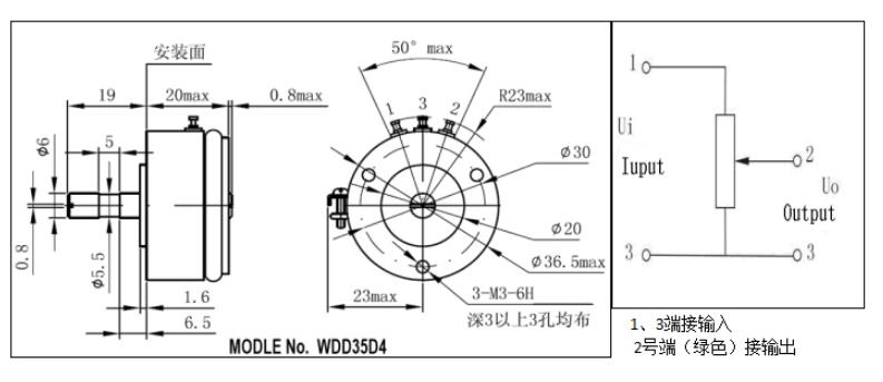
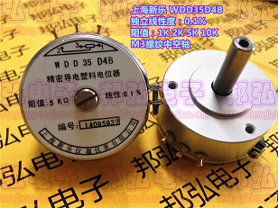
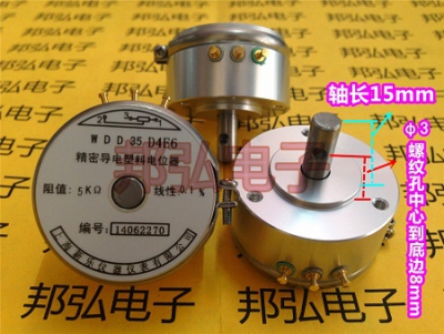
Biến trở xoay, chiết áp nhựa dẫn điện chính xác WDD35D4C1 1K 2K 5K 10K góc hiệu dụng 90 độ
Tình trạng sản phẩm:
Technical parameters:
Performance parameters
■ Resistance value: 1K, 2K, 5K, 10K
■ Resistance value tolerance: ±15%
■ Independent linearity: 1%, 0.5%, 0.3%, 0.2%, 0.1%
■ Electrical angle: 90°±2° (60° ° 120° 180° 270° can be customized)
■ Rated power consumption: 2W ( @70°C )
■ Temperature coefficient: 400ppm/°C
■ Insulation resistance: ≥ 1000MΩ ( 500V.DC )
■ Insulation withstand voltage: 1000V ( AC.RMS )1min
■ Smoothness: ±0.10%
mechanical performance
■ Mechanical rotation angle: 360° continuous
■ Starting torque: ≤1X10^-4 N·M
■ Bearing: two sets
of ball bearings ■ Shaft: stainless steel
■ Housing: aluminum alloy surface oxidation Handling (silver)
environmental performance
■ Mechanical life: 50,000,000 rpm
■ Temperature range: -55℃~125℃
■ Vibration: 15g,
2000HZ ■ Shock: 50g11mS
1. Overview
Conductive plastic angular displacement sensor is a displacement sensor with a linear relationship between voltage output and shaft rotation angle. It is characterized by high precision, long life and good output smoothness.
The structure of the angular displacement sensor is mainly composed of a conductive plastic substrate, a brush, a follower shaft, and a housing.
There are several types of angular displacement sensors, such as single-connection, double-connection and multi-connection. The electrical signal leads are generally in the form of terminals.
2. Installation
2.1 The diagonal displacement sensor is positioned with its own mounting boss, fastened to the metal plate with screws (see the figure above), and then the follower shaft is connected to the center of the rotating body;
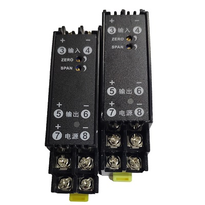
2.2 For the wiring of the angular displacement sensor, see the wiring diagram on the sensor (where "1" = zero phase of the sensor, "3" = input end of the sensor, "2" = output end of the sensor), and the connectors are marked with 1 and 2 , 3 correspond to the schematic diagram; the mid-pump series products have four terminals, please refer to the dimension drawing of the corresponding model for specific wiring.
2.3 The input and output of the angular displacement sensor are both analog DC voltage signals, and the size of its output voltage is determined by the size of the input voltage (eg: input 5V, the output of the entire range is: 0-5V; input 10V, the output of the entire range is: 0-10V, and so on).
3 Notes
3.1 Before installing the angular displacement sensor, users should not disassemble or modify it without authorization (including tearing off the trademark, processing on the shaft and housing, loosening the nails, turning the position of the fastening ring, etc.). During the installation process of the angular displacement sensor, it should be handled with care, so as not to damage the terminal;
3.2 When the angular displacement sensor is connected to the line, it should strictly follow the schematic diagram on the sensor. Pay special attention to the "2" terminal is strictly prohibited from connecting to the input voltage, otherwise the sensor will be burned;
3.3 The recommended current through the potentiometer is 2mA, and the maximum value should not exceed 1OmA;
3.4 The voltage across the input terminals (1, 3) is not greater than 24V;
3.4 The external wiring of the angular displacement sensor should be welded at the waist groove of the lead-out end, and try not to be welded on the top of the lead-out end. When welding, ferrochrome should be used no more than 45W, and the welding time should be less than 5S. When welding and not cooling thoroughly, the wire should not be pulled, so as to avoid the brush wire or the entire terminal being pulled out or even falling off. When welding, use as little flux and welding oil as possible, and the time should be short, so as to avoid the flux vapor from entering the potentiometer through the terminal (green), which will cause the vapor to deposit on the surface of the resistance element after cooling, causing the equivalent noise resistance to deteriorate, or even open circuit;
3.5 The angular displacement sensor should be prevented from being invaded by solvents and corrosive gases. Prevent metal chips or other powders from entering the angular displacement sensor;
3.6 When the angular displacement sensor is powered on, be careful not to measure the potentiometer voltage with the electrical barrier and current gear of the multimeter;
3.7 For the failure of the angular displacement sensor caused by the above reasons, the manufacturer is not responsible for the warranty service.
4 User Notice
4.1 The applied voltage of the angular displacement sensor should be guaranteed to be within the rated power consumption range. Note here that the rated power consumption refers to the allowable power consumption of the potentiometer when the ambient temperature is -55 to 70°C, when the operating temperature exceeds 70°C. The power usage should be reduced according to the curve in Figure 2;
4.2 The accuracy of the angular displacement sensor refers to the compliance accuracy of the output retention, not the deviation accuracy of the total resistance value. The linear accuracy of the angular displacement sensor adopts independent linearity, which is subject to the test calculation when the load is open. Independent linear calculation method: Using the current method of the potentiometer industry, the front and rear zero voltages are specified as the two ends, and the theoretical electrical stroke and the connection between the two ends are determined as the reference straight line. Half of the maximum deviation circle (the sum of the positive maximum deviation and the negative maximum deviation absolute value; the positive maximum deviation and 0 or the negative maximum deviation and 0), as the linear deviation of the potentiometer;
4.3 The installation structure, size, and test calibration point of the double-coupled angular displacement sensor are generally based on the reference unit (first unit). Synchronization accuracy generally refers to the percentage of the difference between the output voltage of the two-connection and the total applied voltage at a certain calibration point (the total applied voltage of the two-connection is the same), rather than the synchronization error of all test points. The calibration point generally selects the starting point or the midpoint (the midpoint of the theoretical electrical rotation angle). The synchronization accuracy is generally 1%, and it can also be at the level of linear accuracy.
Shenzhen Ximis Electronics Co., Ltd. is a professional company that distributes potentiometers, encoders, switches, knobs and other electronic products. Agent distribution brands are: Japan ALPS, TOCOS, COPAL, NOBLE, Panasonic, American BOURNS, CTS, BI, Spectrol, Taiwan TOPVR, DIP, ALPHA... etc .


TÂN THÀNH CAM KẾT
- Sản phẩm, hàng hóa chính hãng.
- Giá cả cạnh tranh.
- Dịch vụ chăm sóc khách hàng tận tâm.
Thông Tin Công Ty
Chính sách và quy định
Đã thông báo

Hỗ trợ khách hàng
THÔNG TIN LIÊN HỆ:
-------------------------------
CÔNG TY TNHH THIẾT BỊ CÔNG NGHIỆP TTH
Trụ sở: số 124 ngõ 79 Yên Hoà-Cầu giấy-HN
Kinh doanh 1 : 0816.861.515
Kinh doanh 2 : 0836.861.515
Kinh doanh 3 : 0926.511.515
Kinh doanh 4 : 0916.861.515
Kinh doanh 5 : 0888.868.515
Kinh doanh 6 : 0917.971.515
Website: http://tanthanh-automation.com
Website: http://thietbitudongtanthanh.com
Website: http://diencongnghieptanthanh.com
Email: tthkinhdoanh@gmail.com
Email: tthkinhdoanh01@gmail.com
